|
||||
|
||||
| In order for anyone to build and program their own ‘Sitcom’, they will need certain tools and facilities to hand. In the case of such single-use items such as an EEPROM / EPROM programmer, it might be easier to borrow or loan one from work / College / Uni / School / a friend, in order to get the Sitcom up and running. Bear in mind that one of the great features of Sitcom, is that all programs are subsequentially written into the RAM via the PC Assembler, thus the programmer will never be needed for it again! |  |
||
| 1) |
|
|||||
| 2) | A simple TEXT EDITOR such as Windows Notepad, or EDIT if using one of the last issues of DOS. Remember that a word processing program like Word or WP will be unsuitable as it will ‘add’ characters to your program listing which will cause serious problems with your Assembler! Other shareware and freeware text editors are available from many sources but not really necessary here. | |||||
| 3) |
|
|||||
| If however, you are happy with the Assembler you are currently using and do not wish to try out the one that San has written, you may have to use an additional TERMINAL PROGRAM to download the code to the Sitcom. (San’s SB-Assembler has this facility already built-in.) | ||||||
| 4) | DOCUMENTATION In order to start programming the Sitcom’s 8085 processor, you will need some suitable documentation. See our DOWNLOADS page for all those essentials. However, for a complete understanding of the 8085 instruction set, a proper programming manual will help a great deal with those more complex programming tasks. | |||||
| 5) |
A BOOT PROM. This is the heart of the 8085 based Sitcom which allows the computer to download your program into the right place and run it. Once again see the DOWNLOADS page for the full program listing, in both binary format and ASM that may be used directly by the SB-Assembler to program an EEPROM or EPROM. As mentioned at the top of this page, a PROGRAMMER will be needed once to write the program into the boot prom. Almost all will accept coding from an assembler such as San’s. I myself used the EEPROM programmer featured on my own site. The PROM device itself may either be a 27256, a 2764 or any of the same sized variants. Incidentally, it goes without saying that San wrote and debugged the boot prom routine on his own SB-Assembler! |
|||||
| 6) |
Bill of materials or BOM One of the essential features of the Sitcom Training Computer was the requirement for ALL component parts to be freely available. |
|||||
|
||||||
|
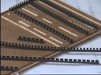
A circuit board to build it on. Either strip board, pad board or one of the Eurocards may be used. Both San and I used a similar sized board, in my case it was the 160mm x 100mm Roadrunner card. Some may wish to use a slightly larger version to allow more room for expansion and power supply components. The basic hardware needed (which it is not necessary to rigidly adhered to ) for this board is as follows: 4x rubber feet with screws and nuts / adhesive. Power connector / socket to suit. Wire and 9 way ‘D’ socket for serial connection (or 25 way if this is what you will use) Two SPST push button switches. Vero pins (optional) for testing / hanging scope or meter probes from. 40 way header for expansion or test modules. One LED (unless you wish to use a second one as a power ‘on’ indicator). IC Sockets. The absolute minimum number is as follows: 2 x 40 pin, 2 x 28 pin, 1 x 20 pin, 1 x 16 pin and 3 x 14 pin DILs. If using one or two optional DL1414 displays you will need another 28 way socket, as well as two further 16 pin ones if the 100Hz divider chain using 4040’s is to be built onto the board rather than the project utilising the mains frequency derived 100Hz/120Hz.
|
|||||||||||||||||||||||||||||||||
|
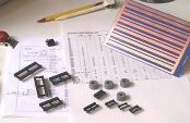
Integrated circuits
|
|||||||||||||||||||||||||||||||||
|
Miscellaneous Components
|
|||||||||||||||||||||||||||||||||
|
| [Home] [Latest News] [Essentials] [Hardware] [The Build] [Programs] [Projects] [Downloads] | |||